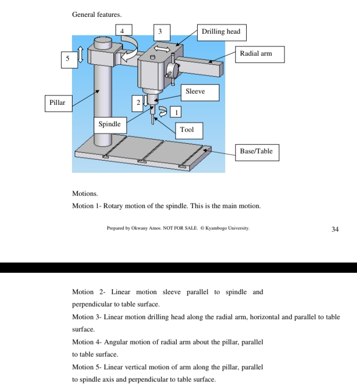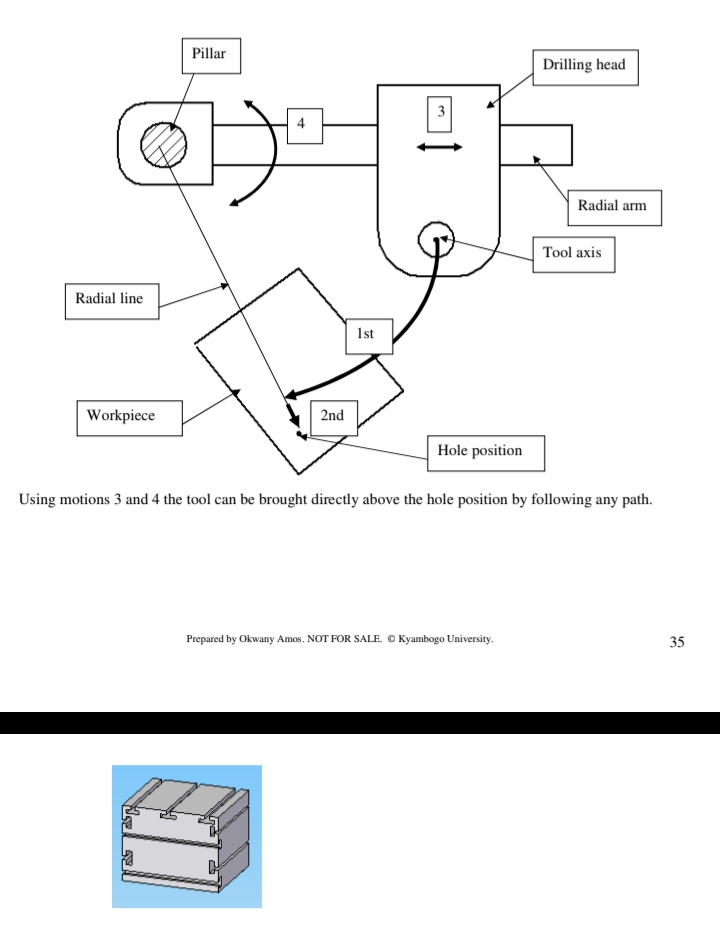
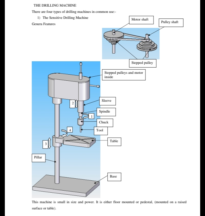
The spindle is powered from a small motor through a stepped pulley to provide four or more different speeds. Power is available only to the spindle rotation. All other motions are manual.
Motions
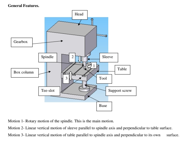
Motion 1- Rotary motion of the spindle. This is the main motion.
Motion 2- Linear motion of sleeve parallel to spindle axis and perpendicular to table surface. This is the only feed motion available on this machine.
Motion 3- Linear motion of table of table perpendicular to its own surface and parallel to motion 2 and spindle axis. This motion is only for setting the position of the table depending on the height of the work piece, tool length and stroke of motion 2.
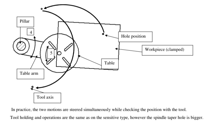
Motion 4- Angular motion of table about pillar axis parallel to its own surface. this motion is for setting hole position directly below tool axis.
Work holding
Handholding
This is recommended for either small drills or heavy work pieces whose weights can stand against the power of the spindle drive. Thin sheets should never be hand held since it can easily be ‘picked’ by the tool and have it rotating with it, endangering the operator’s hand.
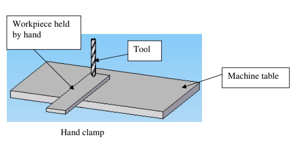
This is for tiny pieces or thin plates where hand grip provides insufficient power to counter that of the spindle power.
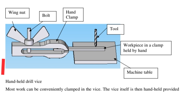
Most work can be conveniently clamped in the vice. The vice itself is then hand-held provided the drill is not too big. Deep holes are produced more accurately since the vice aligns the work piece automatically with the spindle axis and table surface.
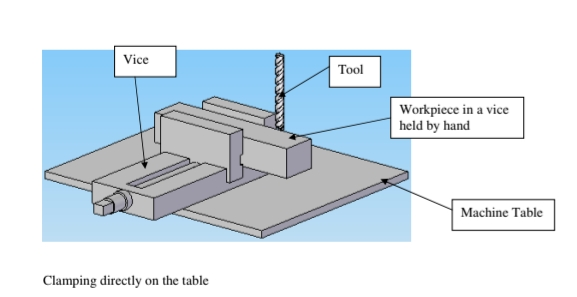
Clamping directly on the table
When drilling big holes, the holding power required is big. If the work piece is of awkward shape it is recommended to clamp directly on the table. This is done using tee-bolts in the tee-slots provided on the table, or using G-clamp.
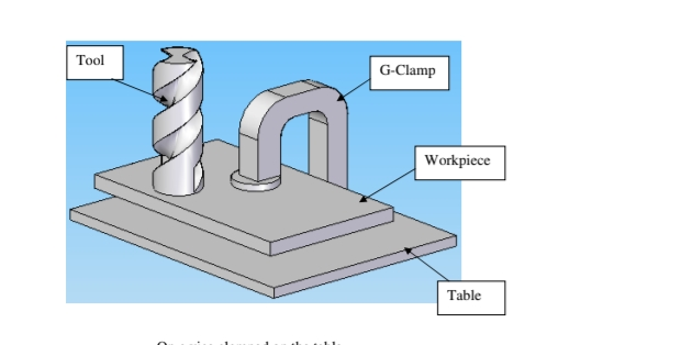
On a vice clamped on the table
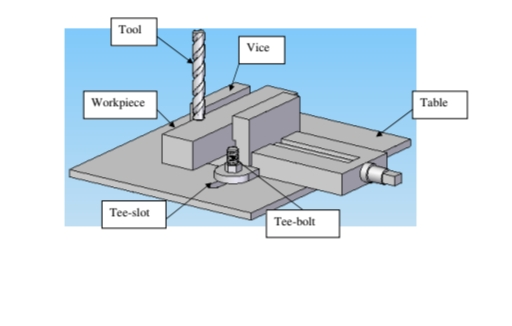
Work piece that can be accommodated in a vice must be held in a vice, and if the cutting power is big the vice should be clamped onto the table using tee-bolts in the tee-slots provided on the table
Tool holding
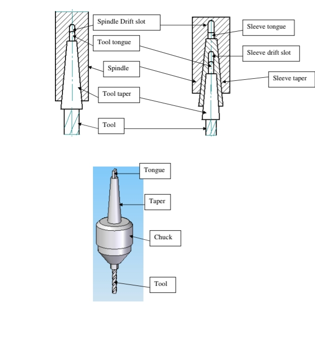
The only tool holding position is the spindle. It is done in much the same way as on the lathe tailstock. The tool however must have the same taper size as that on the spindle. If the spindle taper is big then a sleeve is used to fit in between the spindle and the tool.
Operations
The result of all operations is always a surface of some form produced. This comes about as a generated surface using single point tool or copying the form from the tool onto the work piece.
In both cases it is possible to produce a surface only if at least two motions of the machine are present at the same time. These are active motions, one of which must be spindle rotation, which is the main motion.
Another motion, which is very important but does not exist during actual cutting process is the one used to set the cutting depth. This is passive motion. It is the motion used to give the work piece its size
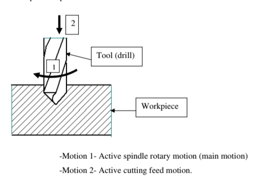
The length or depth of hole depends on sleeve stroke and the position of the table on the pillar below the tool.
All small drills are held in the chuck which fits in the spindle taper.
It is however important to note that small drills are likely to break when exposed to forces bigger than the ones they can handle. This condition is unavoidable when drilling through holes because when the drill is breaking through the other side as it penetrates the work piece, the cut surface area keeps reducing and if the feeding force does not reduce, then the tool begin to take thicker and thicker cuts, known as ‘bite’, which increases load on the tool and may prove too big if not reduced. Since this machine is not fitted with automatic feed, the operator feels (senses) the drill breaking through the work piece because the feeding
force reduces. The operator then reduces the feeding rate and therefore avoids excess force on the tool.
This is why it is called ‘sensitive drilling machine’
All the following operations are carried out in the same way as drilling, with the only difference being the
tool.
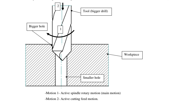
Counter drilling.
This operation enlarges an existing hole.
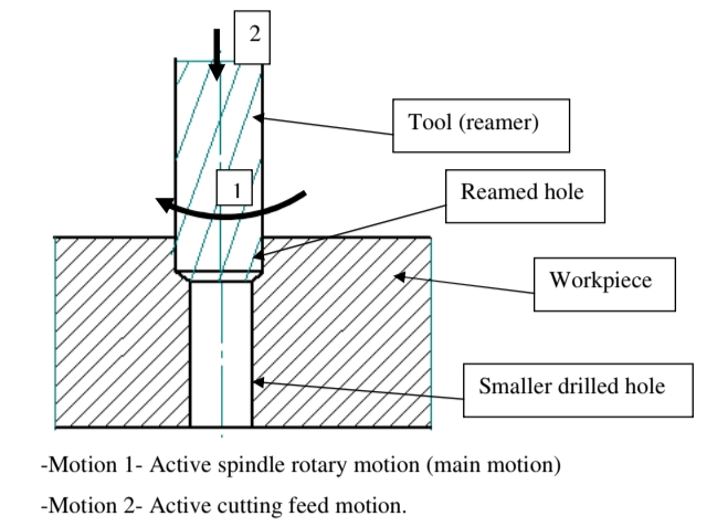
Reaming.
This operation improves the surface finish and size of an existing hole.
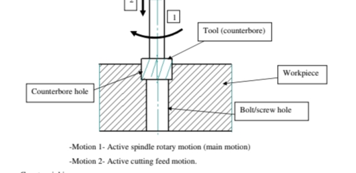
Counter boring.
This operation produces hole with a flat bottom on top of a smaller one. This
becomes a recess for hiding the head of a bolt or screw below a surface.
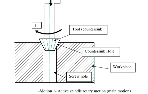
Countersink
This operation produces a counter sink hole on top of a smaller one. This becomes a recess for hiding the
head of a counter sink bolt or screw below a surface.

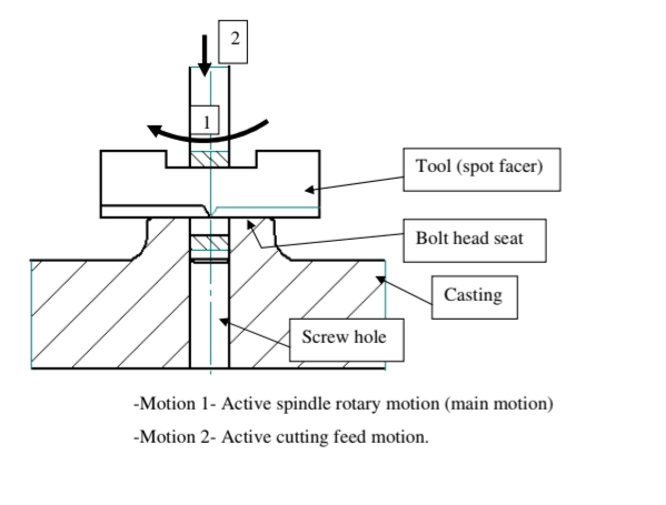
Spot facing.
This operation is for cleaning the top of a hole in a casting. Castings usually have poor surface finish and geometry; therefore, the surface must be cleaned if the bolt head, nut or washer is to sit properly on top of the hole
- To. The Pillar Dril
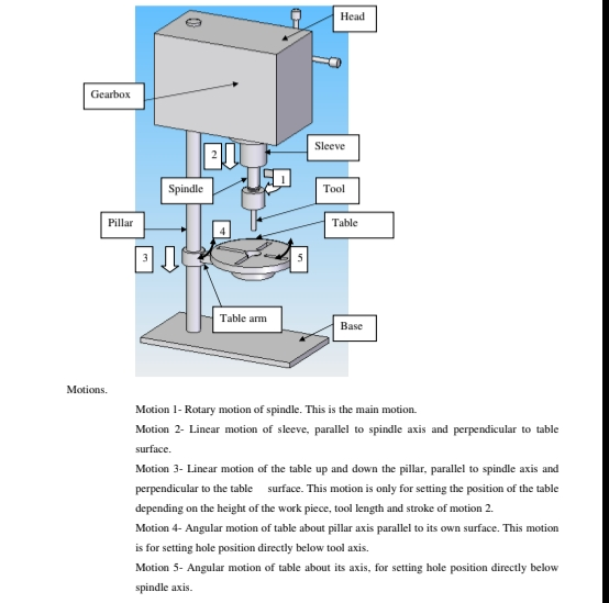
This is a bigger version of the sensitive drilling machine provided with spindle power through gear box
unlike belt driven in the sensitive drilling machine. This is what provides the spindle with the different
ranges of speeds. The table is round and has an additional angular setting motion. Feed motion is also
provided with power.
General Features
Work holding.
All the methods used on the sensitive drilling machine are used here sensibly since the spindle taper is bigger, accepting bigger tools and much bigger vices can be used on this machine. This machine is powerful, with provision to use tools for heavy material removal. Since most of the work done here require huge forces, work holding must be completely restrictive. Tee-slots are provided on the table for this purpose
With the work piece restricted onto the table, putting the hole position below the
tool axis is done as follows:-
- The table arm is released from the pillar lock.
- The table is released to be free to rotate about its own axis.
- With the two motions freed, the hole position can be brought below tool axis as shown in the diagram below:-
- Box Column Drilling Machine
Unlike the pillar type, which stands on a pillar, this machine is supported on a box column for better rigidity. The table is also supported on a height adjustment screw, making the table very rigid, unlike that of the pillar type, which simply hangs on the pillar.
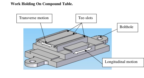
The table is also provided with tee-slots for clamping purposes as on other drilling machines. This machine is however supplied with a compound table, which has two mutually perpendicular motions for very accurate setting of the work directly below the tool. Once the compound table is bolted on the
machine table and the work piece bolted onto the compound table, any position of the work piece can be brought under the tool using the two motions of the compound table.
4. Radial Drilling Machine.
This machine is made of different sizes and power. On this machine, it is the tool which is brought directly above the hole position. Since the work piece is fixed, heavy components can be easily drilled right fromhe floor without any clamping. It is however supplied with two auxiliary tables and therefore making it
possible to preset the work on one table while drilling is going on using the other table, thus increasing the speed of production.