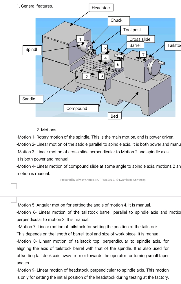
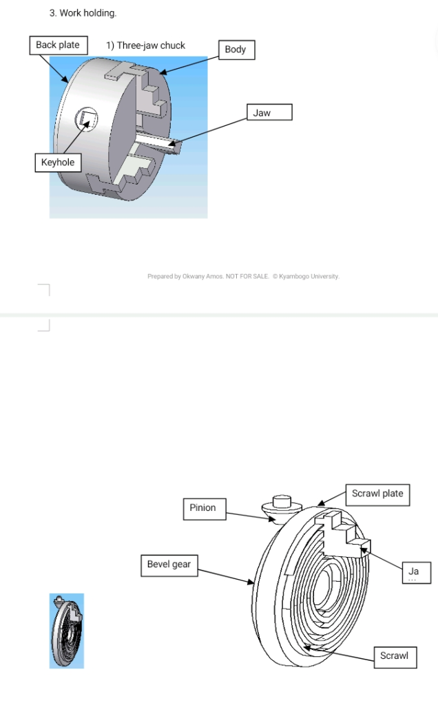
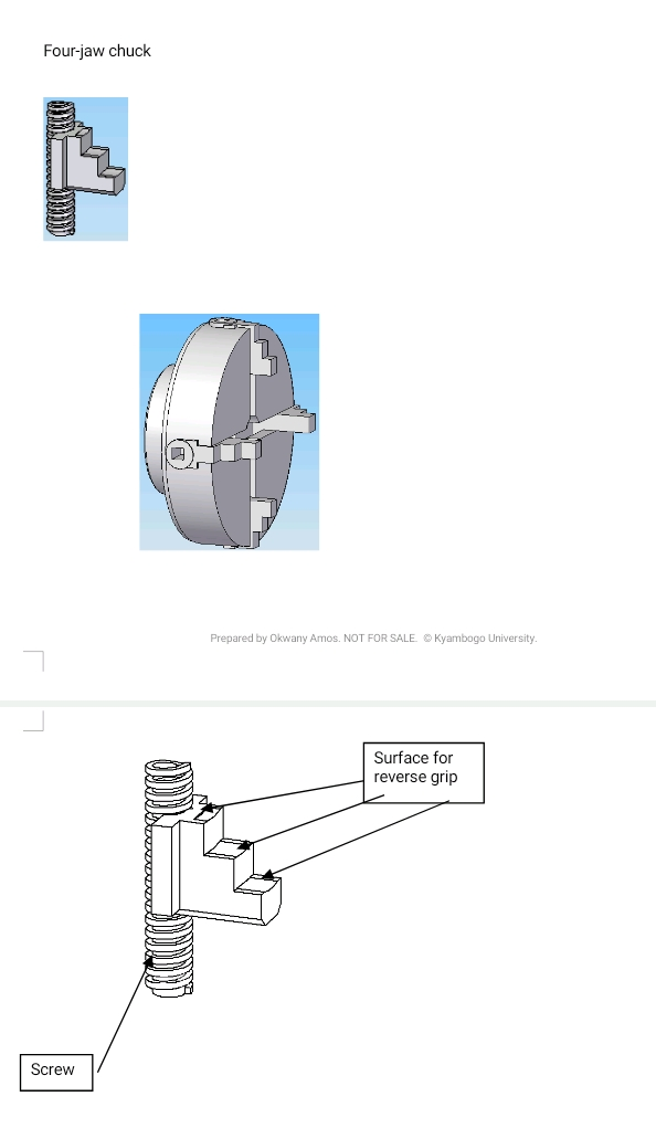
The chuck is fitted on the spindle nose and rotates with it as one. There are three jaws between which the work piece is held. All the three jaws move together at equal distance from spindle axis. The driving arrangement consists of the chuck body, inside which is a scrawl. The scrawl faces the front side of the chuck body where there are three slots acting as guides for each of the jaws. The back of the jaws have grooves which engage with the scrawl, making it possible to move all the three jaws at the same time just by rotating the scrawl relative to the chuck body, about the spindle axis. This is done with the help of a bevel gear pinion with the end protruding outside the body and its bevel gear meshing with a similar one cut at the back of the scrawl plate. Outside the chuck body, at the end of the pinion is a blind square hole in which a key is inserted and therefore it becomes possible to turn the pinion and rotate the scrawl plate on which is the scrawl itself. Because of the grooves at the back of the jaws, and the slot guide at the face of the body, the jaws acquire linear motion towards the center or away from it, depending on the direction in which the key is rotated. This work holding method is reliable only when the chuck is still new. With time, moving parts of the system and the contact points of the jaws themselves do wear, and because of the non-uniform nature of wear, the jaws lose concentricity, that is, the equal distance of the jaws from the center, get lost. It therefore becomes impossible to machine a surface concentric to the one held in the jaws. All attempts must therefore be made to do all necessary machining on a component in one setting when using this chuck. It is otherwise very easy and fast to set work on this chuck.
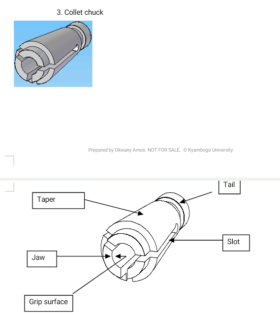
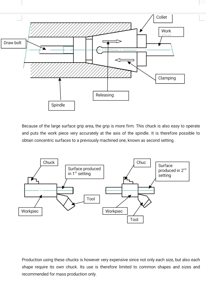
This chuck fits in a taper at the spindle nose. It also has a matching taper and a tail, all accurately ground in one setting with the grip points. This makes it possible for the spindle, chuck and work piece to run concentric. Slots are provided to facilitate clamping. Clamping of the work piece is effected by drawing the chuck into the spindle nose taper using a draw bolt inserted through the back of the spindle. When the draw bolt is released, the jaws spring open and release the work piece because the chuck is made from spring material.
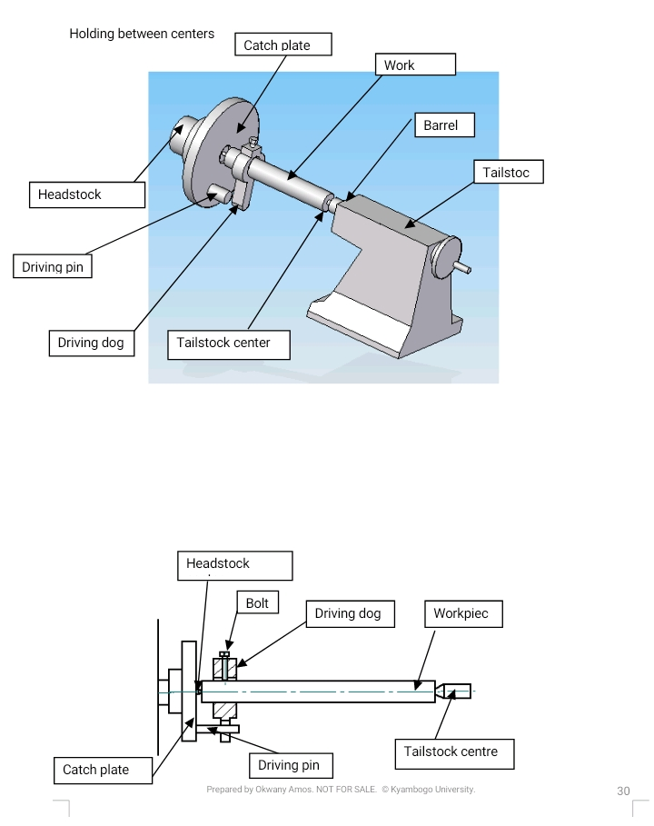
In order for holding to be possible between centers, it must have center drill holes at both centers, and these holes must be acceptable in the final product. It must also be of a length, which can be accommodated between the centers. One center is at the headstock (live center) and the other one is at the tailstock center (dead center). A driving dog is dressed on the work piece and held on it by menace of a bolt, making them able to move as one. This is possible through the driving pin on the catch plate fitted on the spindle nose and therefore rotates with the spindle. Since the work is supported between centers, it is possible to remove it and quickly put it back at axis of spindle rotation without the need of any special setting process like is the case with the four-jaw chuck.
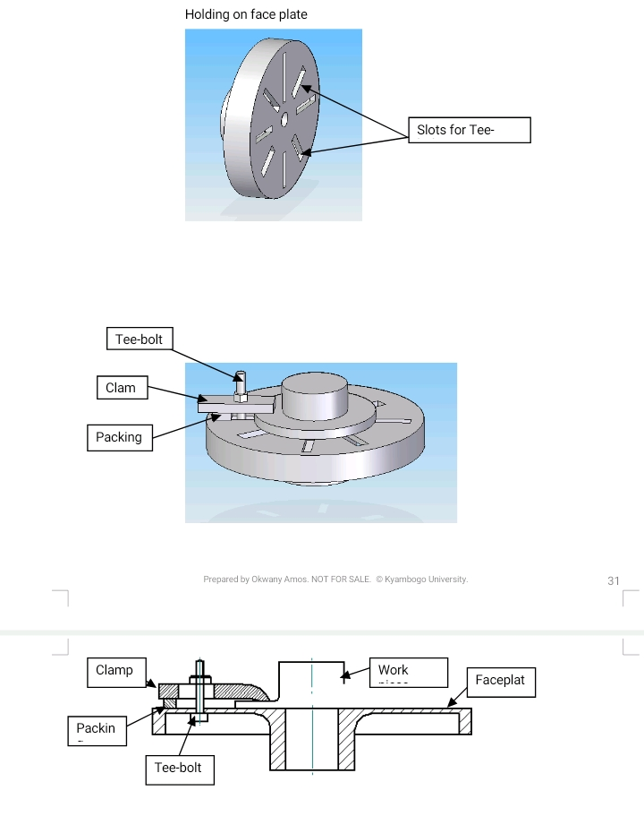
This is a round plate with a flat surface. It is provided with slots, used for bolting or clamping the work piece onto the plate using tee-bolts. The plate fits on the spindle nose and therefore rotates with the spindle. Setting work on this plate requires great skill and takes time. However it provides a method of machining pieces of awkward shapes, which are impossible to hold using other means. Since work held in this way is usually irregular, the spindle is always left unbalanced, and balancing is necessary using appropriate weight opposite the heavier end of the plate. Clamps are used for this.
Depending on the size of the work piece, which is usually huge, the forces on the spindle are big, even after balancing. Only slow speeds should therefore be used.
4. Tool holding.
Tools can be held either in the tool post or at the tailstock
There are three types of tool posts in common use. One-way tool post, four-way tool post and American tool post.
The tool is clamped onto the tool post using the bolts provided and the tool post itself is bolted down onto the compound slide. The tool therefore move as one either through the saddle or cross slide or the compound slide itself.
One-way tool post is used on a mass production machine and is not provided with tool height setting since this can be achieved through careful tool size choice and grinding. The four-way tool post is used on universal machine tools variety, for machining take place using any available tool and therefore must have provision for tool height control.
The American tool post is also for universal machine tools. A rocking tool rest is used for tool height control. This method tends to affect the rake angle of the tool. This must be taken into account when grinding the tool, depending on the material being machined.
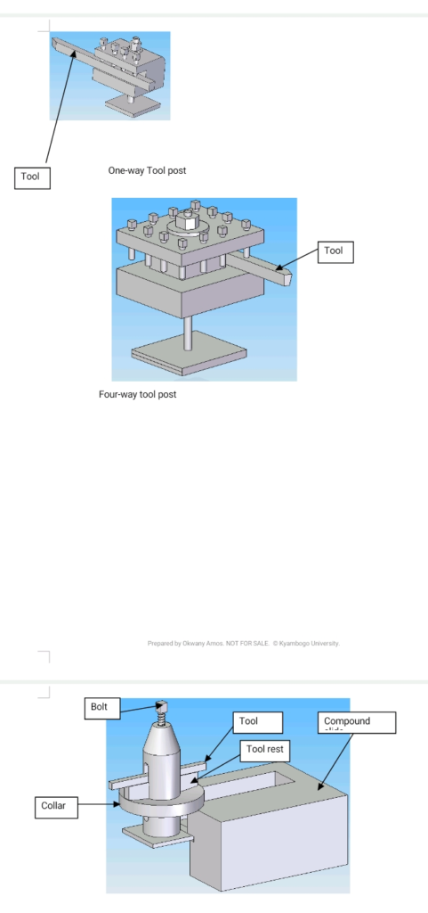
American Toolpost
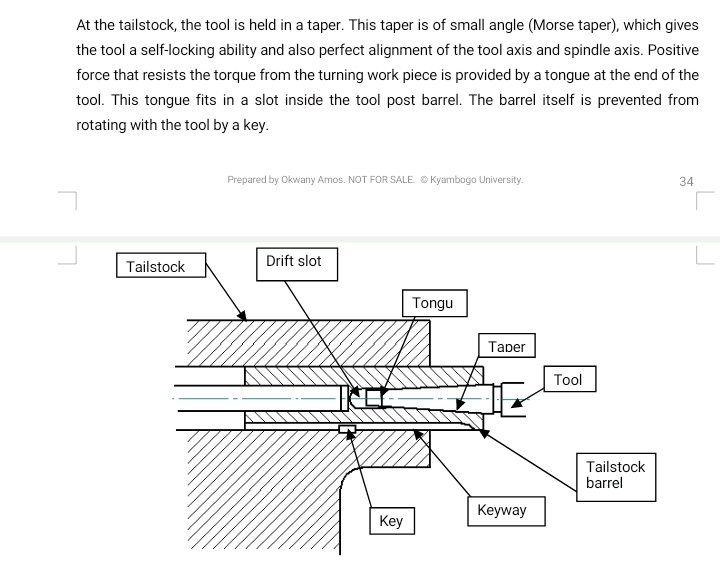
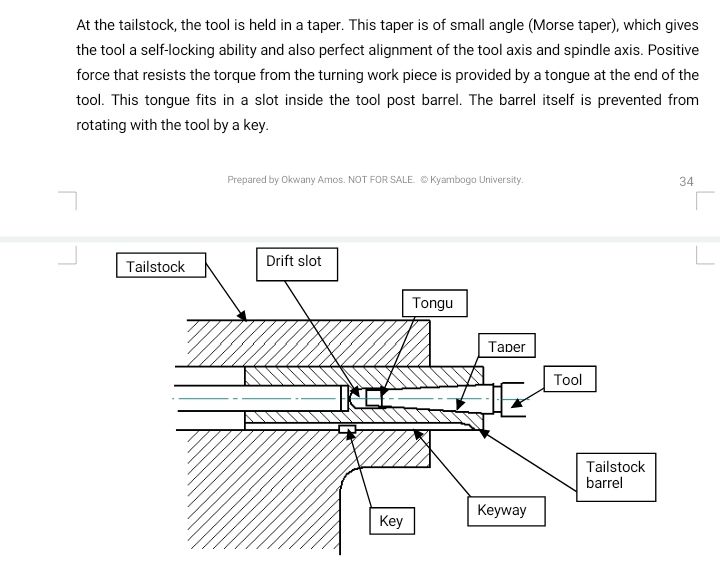
At the tailstock, the tool is held in a taper. This taper is of small angle (Morse taper), which gives the tool a self-locking ability and also perfect alignment of the tool axis and spindle axis. Positive force that resists the torque from the turning work piece is provided by a tongue at the end of the tool. This tongue fits in a slot inside the tool post barrel. The barrel itself is prevented from rotating with the tool by a key.
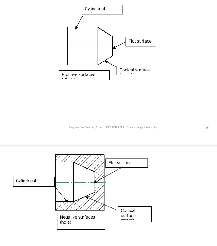
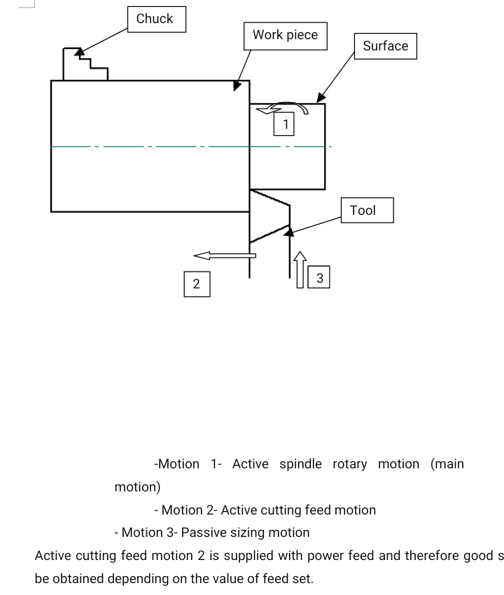
The result of all operations is always a surface of some form produced. This comes about as a generated surface using single point tool or copying the form from the tool onto the work piece.
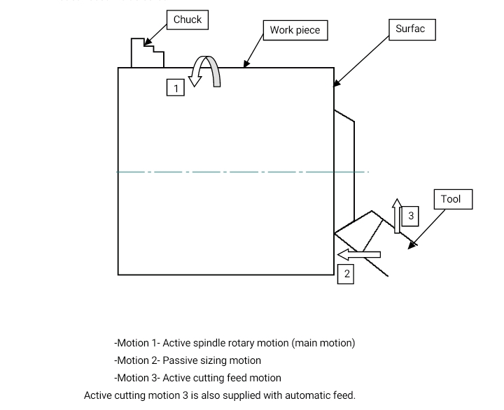
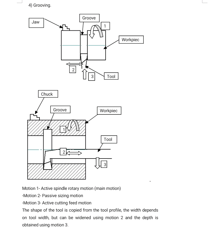
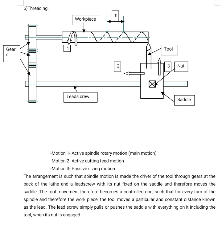
In both cases it is possible to produce a surface only if at least two motions of the lathe are present at the same time. These are active motions, one of which must be spindle rotation, which is the main motion. Another motion, which is very important but does not exist during actual cutting process is the one used to set the cutting depth. This is passive motion. It is the motion used to give the work piece its size.
Tool post operations.
These are operations, which are carried out with the tool at the tool post.
Turning.
This operation produces a positive cylindrical surface, a shaft.
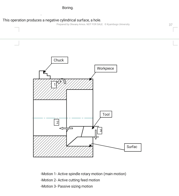
This operation produces a positive or negative flat surface. The tool should be correctly ground
Facing.
This operation produces a flat surface. and the tool should be correctly ground for especially for
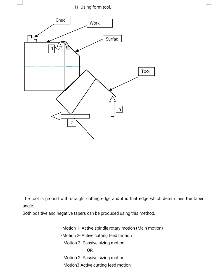
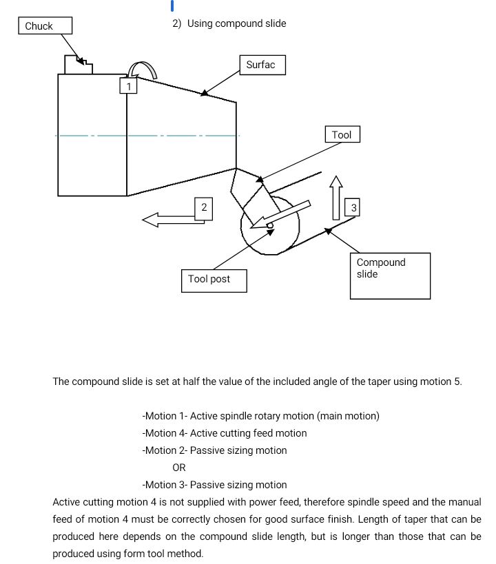
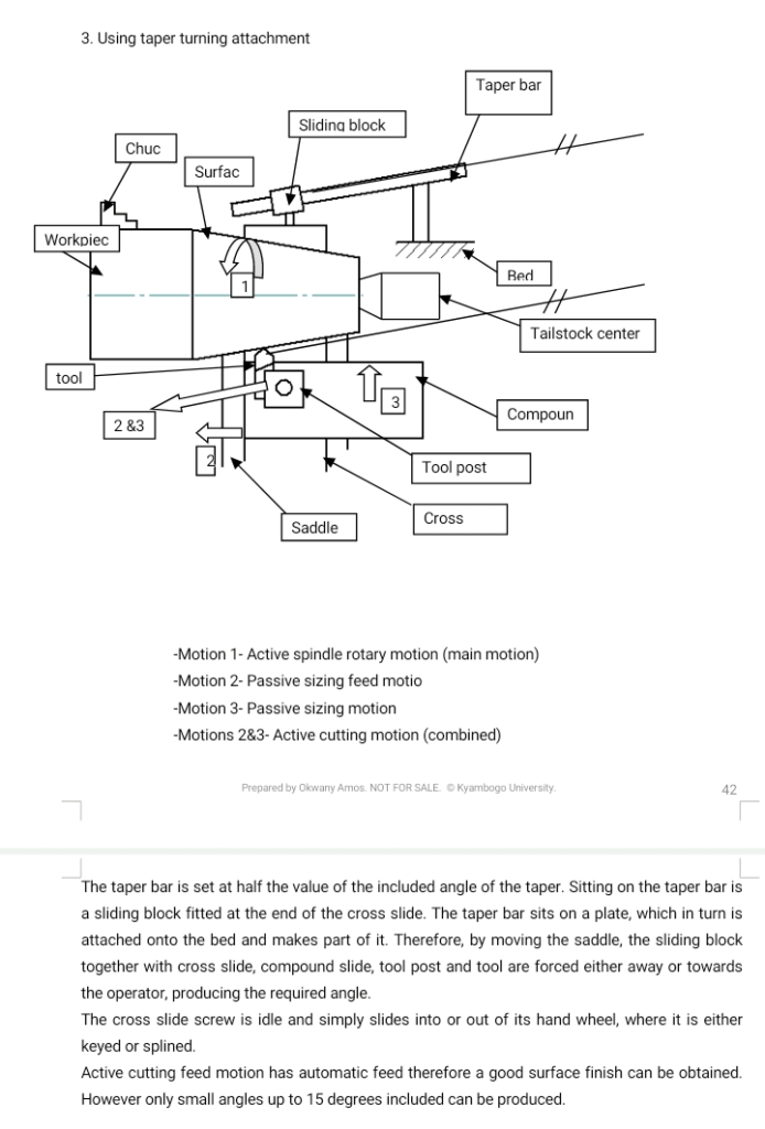
Taper turning
This can be done in three ways.
Tailstock operations.
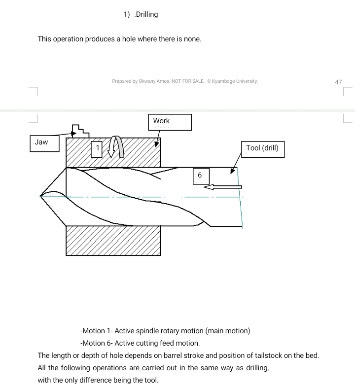
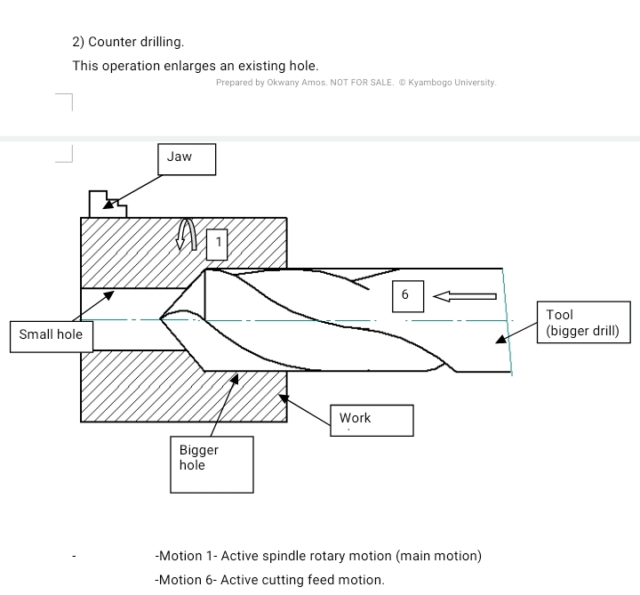
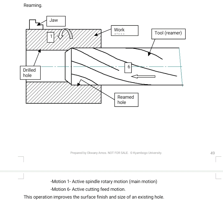
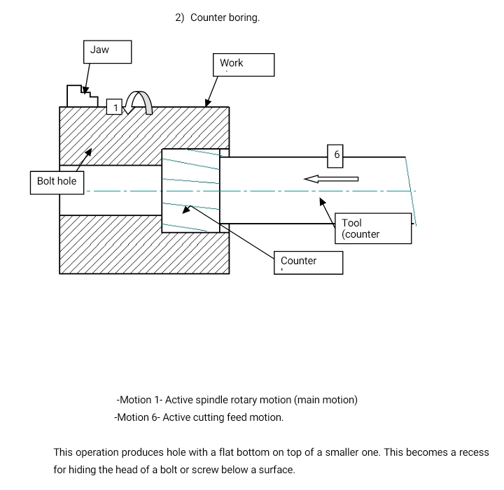
These are operations, which are carried out with the tool at the tailstock.