Prepared by Okwany Amos.
Kyambogo University.
Traditionally, any machine we see is produced with the he help of another machine. These machines which are used to produce other machines are called MACHINE TOOLS.
The very first machines however were manually made by highly skilled men who could work within the required accuracy.
With time however, higher and consistent degree of accuracy came into demand, together with greater forces required, and with increased rate of production due to demand, machines became a requirement in the production process.
INTRODUCTION TO DIMENSION CONTROL AND INSPECTION
Any complete machine is composed of numerous parts, which are produced separately and then assembled. The processes of producing each of those parts involve careful dimension control to suit the required type of fit. When assembled, the two parts are fitted while bearing either of the following two
points in mind:-
- A fit that allows relative movement between the two ( clearance fit)
- A fit that does not allow relative movement between the two (interference fit)
There are three ways of achieving this.1Using individual assembly method,2Using selective assembly method,3Using Systems of Limits and Fits.
INDIVIDUAL ASSEMBLY
In this approach, one of the two parts to be assembled is first machined as close as possible to the required dimension in the working drawing. The second part is then machined while testing using the first piece until when the required fit is attained (clearance or interference).
The disadvantage of this method is that it is slow due to the numerous stoppages required for the frequent checks. It also needs highly skilled personnel for operating the machine. The parts are made for each other and may not fit properly with any other part made for the same purpose. All the above reasons make this
method very costly.
SELECTIVE ASSEMBLY
This approach takes into account the fact that it is impossible to produce a particular size on many components and be consistently exact, yet the small variations do not necessarily render the work piece useless. All parts with sizes that fall within acceptable range (tolerance) must therefore be used by selecting the pairs, which fit with each other for the required fit (clearance or interference). P
For this reason, all parts produced are carefully measured to find out the range of sizes in which they fall.
It therefore becomes possible to sort them according to sizes that fall within the same range and therefore be able to determine which ones do produce the right fit when assembled.
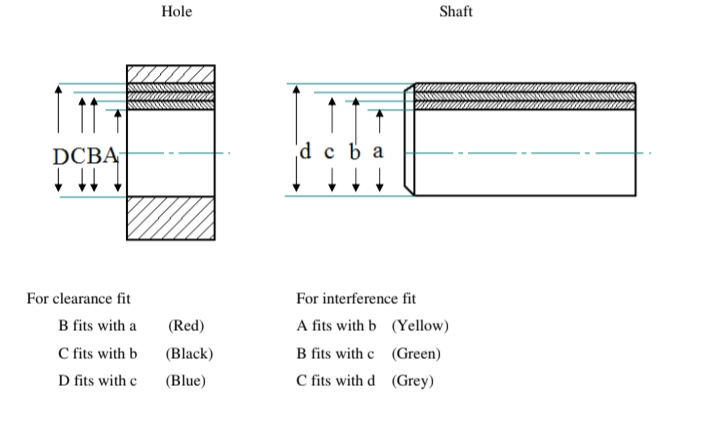
Holes and shafts of particular ranges of sizes are separated in groups, which are marked, tagged or color-coded to make them readily identifiable. Groups of shafts and holes, which give the right fit when assembled, bear the same mark, tug or color code.
Much as this method may not require very high skill from a machine operator, making it slightly faster, it demands very high skill at the sorting stage, with measuring instruments of higher degree of accuracy. These
instruments are also expensive.
Because parts are selected according to groups during assembly, for machines produced using this method,
Replacement of broken parts during repair are done by replacing the part with a whole assembly, which includes the broken part. If for example, if the hole is worn out and the shaft is still in good condition, even the shaft is replaced.
SYSTEMS OF LIMITS AND FITS
In this method, sizes of all components are determined by the designer at the designed stage and given limits within which a particular size on a component must fall.
All these take place in the mind of the designer only. It becomes known to any other person only after the designer has put it down in drawing. This however can be transformed into components only if the designer produces a working drawing with the right limits determined by him.
What are limits?
Because of machine error that depends on the machine condition and human error that depends on several factors, it is impossible to do machining and produce a size and say with certainty that the size obtained is
the actual size, because even if the size has actually been got, there is human error in taking the measurement from the workpiece onto the measuring instrument and another in reading correctly to get the size indicated on it. On top of that is the error of the instrument, which depends on its accuracy.
The problem is even compounded when dealing with hard materials like metals, since small size variations in the order of thousands of a millimeter do matter a lot at assembly stage, and obtaining the right fit may not be possible.
This is why setting limits is very important. It is only the designer who knows what limits to set for a particular size in order to obtain a fit, which works best on the machine when properly assembled.
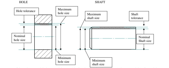
Dimension control during material removal is directly related to the amount (volume or weight) of material that remains on the final product (the component). Therefore, by setting limits, the designer sets the maximum and minimum size (and therefore weight or volume) of a component. This makes it possible to produce from one working drawing any number of that component, and all of them will be acceptable to the designer as long as their sizes fall within the limits specified in the working drawing.
The implication is that the component has conditions of maximum amount of material acceptable (maximum metal condition), and minimum amount of material acceptable (minimum metal condition).
It is then up to the machine operator to use the working drawing and produce components with sizes that fall within these limits for them (the components) to be acceptable.
There are three ways of controlling the sizes:-
- Direct measurements using measuring instruments of the right accuracy.
- Gauging using limit gauges.
- Comparing using comparators.
DIRECT MEASUREMENTS
In order to produce components whose sizes lie within the specified limits, the machine operator must not only know how to operate the machine for metal removal purposes, but also know how to take measurements properly using the instrument, and read the instrument down to the required accuracy. In this process, the operator stops the machine after passes of metal removal and takes the size of the remaining material (shaft or hole). The main aim is to see if the size falls within the one specified in the drawing. However with each pass of metal removal one of the following three situations is likely to result in both shaft and hole cases:-
For shafts,
- The size is above the upper limit, meaning that the component is not yet acceptable
because the weight or volume is still more than the one specified and the metal removed is insufficient. The next action from the operator is to remove more material. - The size is within the limits, meaning that sufficient metal has been removed and the
component is acceptable. The next action is to remove it from the machine and it is ready for use or storage. - The size is below the lower limit, meaning that the metal removed is in excess and
the component has less weight or volume than the one specified. The next action is to remove the component from the machine and discard it off, it is scrap.
For holes,
- The size is above the upper limit, meaning that the material removed is in excess and
the component has less weight or volume than the one specified. The next action is to remove the component from the machine and discard it off, it is scrap. - The size is within limits, meaning that sufficient metal has been removed and the
component is acceptable. The component is removed from the machine and it is ready for use or storage. - The size is below the lower limit, meaning that the component is not yet acceptable
because the weight or volume is still more than the one specified and the metal removed is insufficient. The next action from the operator is to remove more material.
The main thing to note about direct measurement is that the actual size of the component is known because
the operator reads it on the instrument to make sure that it falls within the required limit before accepting it. The operator must therefore be highly skilled.
The next two methods however only check whether or not the size falls within the specified limit. The operator does not know the real size.
GAUGING
This is done using a special instrument called gauge, which has two sizes available on it. One size corresponding to the upper limit and the other one corresponding to lower limit. It is therefore possible to
gauge using this instrument to see if the size produced on the component falls within the specified limit before accepting it.
Using this method requires many gauges since every size must have its own gauge with the right limits.
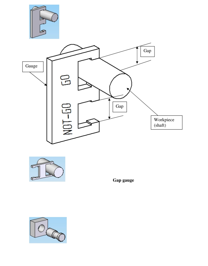
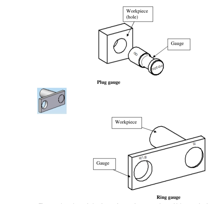
The gauge is put in use during the metal removal process at the machining stage by the operator.
After some metal removal passes, the operator offers the GO side the gauge to the size being machined on the component. In so doing, the operator is expecting this side of the gauge to be accepted at the machined dimension. The process goes on in conjunction with metal removal until this side actually goes. This then marks the end of metal removal process for this dimension.
The big question is whether or not the size obtained falls within the limits specified by the designer. The answer to this question depends on what happens when the NOT-GO side of the gauge is offered to the same size on this work piece being machined and the work piece is still on the machine. This is what the
operator wants to find out immediately, so he offers the NOT-GO side of the gauge to the dimension expecting it to either GO or NOT-GO depending on how much material he took care to remove in the last metal removal pass during the time he was checking the size using the GO side of the gauge. This is a crucial decision making moment and is done only by the machine operator who must interpret correctly the status of the work piece when the NOT-GO side of the gauge is offered to this machined size, he must also be sincere because any bad component taken as acceptable at this stage will be very difficult to detect with the naked eye. The effect can only be felt when it is put to use.
The act of checking with the NOT-GO side of the gauge is to make sure that this side of the gauge actually does not go, for the component to be acceptable because it will mean that the size produced as a result of metal removal in the last pass falls within the required limits.
If it happens so (does not go), the component is removed from the machine as a finished product, which is ready for use or storage.
The other observation expected by the operator when checking with the NOT-GO side of the gauge is for this side to also go the way the GO side did go. This would mean that the amount of metal removed in the last metal removal pass was in excess of what he should have, and therefore the size produce as a result falls outside the required limits. The component is a reject (SCRAP).
Since all components are made from some material whose original weight or volume is either equal or more than that of the component, it is not difficult to see that the condition in which the original material,
the work piece, is left in is either the same or less in weight or volume. Where metal removal is not involved only the shape or the original material changes whereas both weight and volume remain the same. This means that the condition of the original material has not changed in terms of weight and
volume. However where metal removal is involved, both weight and volume must reduce. Sizes therefore play a big role in determining metal condition of the finished component in terms of weight and volume.
The limits set by the designer, in fact, set the maximum and minimum metal condition of the component.
These two conditions are therefore very easily checked using the gauge since the GO gauge checks the maximum metal condition acceptable by the designer and the NOT-GO gauge checks the minimum metal
condition allowed. This is true for ALL gauges be it for shafts or for holes. Dimension control using gauges does not require high skill and it is fast and easy. However, the initial cost or capital input is enormous due to the total cost of gauges required since each size requires a separate gauge and gauges are very expensive. This method of dimension control is recommended only for mass production.
COMPARATORS
Comparators are more advanced measuring instruments, which are used, for either inspection in mass production of components produced using universal machine tools, or continuous dimension control in
automatic machines tools or machining centers.
Their working principle is basically comparison. For a given dimension, the instrument is set using two sample pieces. One sample piece has the actual size equal to the upper limit size of the component and another sample with the actual size equal to the lower limit size of the component. Since the two sizes are
different, the indicator on the instrument will assume one position when the sample with lower limit size is used and another position when the sample with the upper limit size is used. The signal from the sample is
magnified, making it possible to see with the naked eye the difference between the sizes of the two sample pieces. This becomes a zone that represents the limits set by the designer on the working drawing. It therefore becomes very easy to compare the size of a component with the ones used for setting the two
limits. Any size, which falls within the zone, is acceptable. Those that fall outside the zone are either corrected or scrapped.
In existence are mechanical, electrical, pneumatic and hydraulic comparators. Attempts are made to make the zone clearly visible using color zone or color liquid.
It is obvious, the fact that these instruments are very expensive although very easy to use and are very accurate. Just like in the case of using gauges, comparators are used only for quality control and mass production.
What are fits?
Parts are made to work together after assembling a complete machine. During assembly, the worker must pay attention to the fact that some parts are assembled to allow relative movement between each other and
others do not allow relative movement.
In individual assembly, this is taken care of by the machine operator who is himself skilled.
In selective assembly, this is done at the sorting stage where parts are matched or selected and color-coded for storage. It is important to note that there are no rejects here since all parts are matched according to
how they fit best.
In the system of limits and fits however, this is taken care of at the design stage by the designer who sets limits for every size. Therefore, ALL parts produced within their limits are interchangeable, and will fit
perfectly during assembly and fully serve the purpose for which the machine was designed. This is because only parts whose sizes fall within the limits set by the designer are cleared as good by the machine operator.
There are three types of fits technically known as CLEARENCE FIT, INTERFERENCE FIT and
TRANSITION FIT.
The term FIT refers to shaft assembled with hole to produce either relative movement between each other or no relative movement at all between each other. The designer knows where relative motion is required and where it is not required. He therefore sets limits, which guarantees either free movement or no
movement in the right places.
It is therefore logical to try to see what goes on inside the designer’s mind at this stage by studying the types of fit in detail.
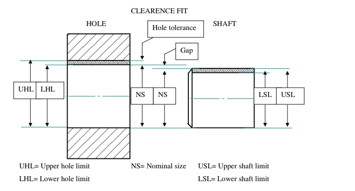
The tolerance zone of the hole is above that of the shaft and between them is a gap, which is a minimum allowance chosen by the designer to guarantee clearance fit between the two during assembly. Clearance fit is therefore an imaginary arrangement of shaft and hole working drawings brought together and assembled to show that the largest acceptable shaft is still smaller than the smallest acceptable hole or the smallest acceptable hole is still larger than the largest acceptable shaft. Designers know that this fit allows
relative movement between the two parts.
Since any shaft or hole, whose size falls within the limits is acceptable it can easily be seen that the minimum clearance allowance possible for this fit is the difference between the smallest hole and the biggest shaft, and the maximum clearance allowance is the difference between the biggest hole and the smallest shaft. The magnitude of the allowance is very important and the designer takes care to make sure that the minimum allowance is there but as small as possible and the maximum allowance is big enough but does not affect the performance of the assembly. When clearance allowance is too big, some parts acceptable as good do assemble with too much ease to make very loose joints with short life span and very noisy when put to use.
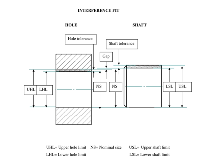
The tolerance zone of the hole is below that of the shaft and between them is a gap, which is a minimum allowance chosen by the designer to guarantee interference fit between the two during assembly.
Interference fit is therefore an imaginary arrangement of shaft and hole working drawings brought together and assembled to show that the smallest acceptable shaft is still larger than the largest acceptable hole or the largest acceptable hole is still smaller than the smallest acceptable shaft. Designers know that this fit does not allow relative movement between the two parts.
Since any shaft or hole whose size falls within the limits is acceptable, it can easily be seen that the minimum interference allowance possible for this fit is the difference between the biggest hole and the smallest shaft, and the maximum interference allowance is the difference between the smallest hole and the biggest shaft. The magnitude of the allowance is very important and the designer takes care to make sure that the minimum allowance is there but as small as possible and the maximum allowance is just enough and does not affect the assembly process or the performance of the assembly. For interference allowance, when Hole tolerance and Shaft tolerance Gap is too big, some parts acceptable as good are impossible to assemble and if they do, the component with the hole is overstressed leading to either its cracking or excess strain to adjacent moving parts like balls or rollers of bearings. This can affect the performance of the assembly in many ways. Usually the efficiency is reduced and there is overheating which can drastically reduce the life of the machine. It also overloads the prime mover.
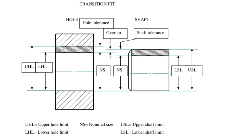
The tolerance zones of hole and shaft overlap. Transition fit is therefore an imaginary arrangement of shaft and hole working drawings brought together and assembled to show that the biggest hole is bigger than the
smallest shaft and the smallest hole is smaller than the biggest shaft.
Designers know that this fit exists only on the working drawing because in reality during assembly only clearance and interference fits are obtained with no effect at all on the performance of the machine.
Since any shaft or hole whose size falls within the limits is acceptable, it can easily be seen that the maximum clearance allowance possible for this fit is the difference between the biggest hole and the smallest shaft, and the maximum interference allowance is the difference between the smallest hole and the
biggest shaft.
Because of the overlap between the hole and shaft tolerance zones, there is no minimum clearance or minimum interference. Theoretically, however there is a possibility of obtaining zero clearance or Hole tolerance
overlapping Shaft tolerance
interference. This happens only if the shaft and hole are of the same size, and is possible only within the area of tolerance zone overlap.
SYSTEMS OF FIT
When shafts and holes are produced on machine tools available to the designer, tolerance limits can easily be controlled to produce components with the sizes required for the right fit. Machine building however
involves the use of ready-made components like bearings and plain shafts. The designer then finds himself in a situation where he can control the limits of only one of the two parts involved in the fit. Holes are also produced easily and more accurately using standard size tools like reamers. Systems therefore refer to the methods used to obtain the required fit, either clearance or interference, when one size is already available and on machining operation is required, or when one size is produced using a standard size tool.
There are two systems for obtaining fits and they are based on either the hole or the shaft depending on which one is already available with its fixed size.
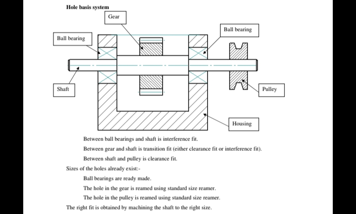
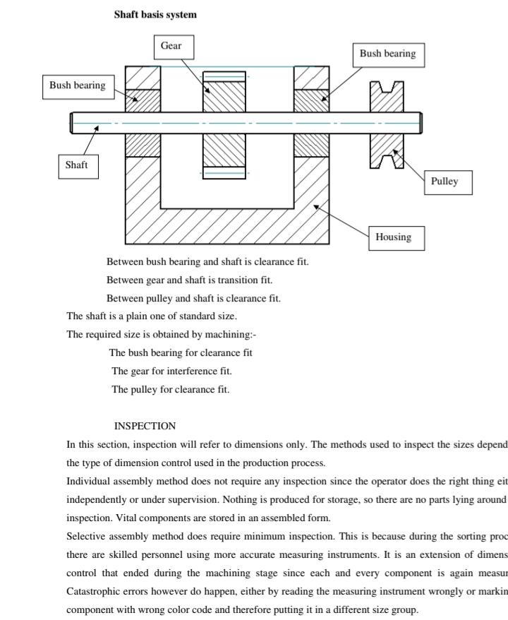
INSPECTION
In this section, inspection will refer to dimensions only. The methods used to inspect the sizes depend on
the type of dimension control used in the production process.
Individual assembly method does not require any inspection since the operator does the right thing either
independently or under supervision. Nothing is produced for storage, so there are no parts lying around for
inspection. Vital components are stored in an assembled form.
Selective assembly method does require minimum inspection. This is because during the sorting process
there are skilled personnel using more accurate measuring instruments. It is an extension of dimension
control that ended during the machining stage since each and every component is again measured.
Catastrophic errors however do happen, either by reading the measuring instrument wrongly or marking a
component with wrong color code and therefore putting it in a different size group.
Bush bearing
Shaft
Gear
Bush bearing
Pulley
Housing Prepared by Okwany Amos. NOT FOR SALE. © Kyambogo University. 16
The use of limits and fits system however require strict inspection since the parts made within limit are
assumed to work interchangeably with any other part made within limits for it. Because of this
interchangeability concept, parts that are passed as good by the worker are taken straight for use or storage
for sale.
Bearing in mind the fact that the workers are semi skilled, inspection methods used should minimize or
bring to zero the number of bad components accepted as good and therefore put to use, sold or stored.
Here the most common approach is the use of gauges. The inspection gauges are more accurate than the
ones used during production. Since gauges are also manufactured, they are also given tolerances, but the
tolerance zones of inspection gauges are smaller and fall within the tolerance zones of the size being
checked.
The GO side of the gauge always wears with time and begins accepting holes of smaller
sizes and shafts of bigger sizes.
This can be minimized or brought down to zero using different methods, depending on the volume and
method of production. In general, active GO gauges should never be allowed to wear up to the maximum
tolerance size limits of shafts, and minimum tolerance size limits of holes. Gauges must therefore be
checked frequently using very accurate measuring instruments and replaced before they begin to accept
sizes which are outside the tolerance limits.
The other approach is random sampling of finished components and replacing the measuring gauge if a
size is found to fall close to the extreme limits of the sizes.
In this case, there is a possibility of a wrong size slipping through to assembly line, or even Sales
Department.
In the assembly line, these cases are spotted out and handled either individually or selectively. However in
the Sales Department, this is a source of bad reputation, which must be avoided at all costs.
Modern approach in production has introduced methods which require constant monitoring of sizes as they
are being produced, and the measuring instruments best suited for this are comparators. They are fitted
directly on the machine, making the constant size monitoring process possible.
Once the machine is set for a particular size, only tool wear remains basically the only factor in the size
variations. As shafts become bigger and holes become smaller, a signal that switches off the machine is
sent from a command within the machine before sizes that fall outside tolerance limit zone are produced
and the tool is replaced.
Elements of inspection here are therefore the settings on the machine and the settings on the tool, and all
parts produced are absolutely interchangeable and can be used, stored or soled without any worry.
MACHINING PRINCIPLES AND METAL CUTTING TOOLS
The following are daily life principles that equally do apply to machining of metals and cutting tools:-
- For any tool to be able to cut another material, the tool must be harder than that material,
just like knife cuts bread because it is harder than bread. - Two materials or objects will never occupy the same space at any one given time. If an
attempt is made to force them into that one space, there must be collision or accident and
the stronger material displaces the weaker one and occupies the space. - The tool must have angles around the cutting edge to make the cutting edge stand alone in
space so that it touches the material at the cutting edge only for maximum cutting or tearing
effect. - There must be an effective work holding provision, a device that leaves the work firm and
rigid on the machine. - There must be an effective tool holding provision, a device that leaves the tool firm and
rigid on the machine. - There must be controlled motions on the machine, to force work and tool into each other,
with contact between work piece and tool at cutting edge only.
TOOL ANGLES
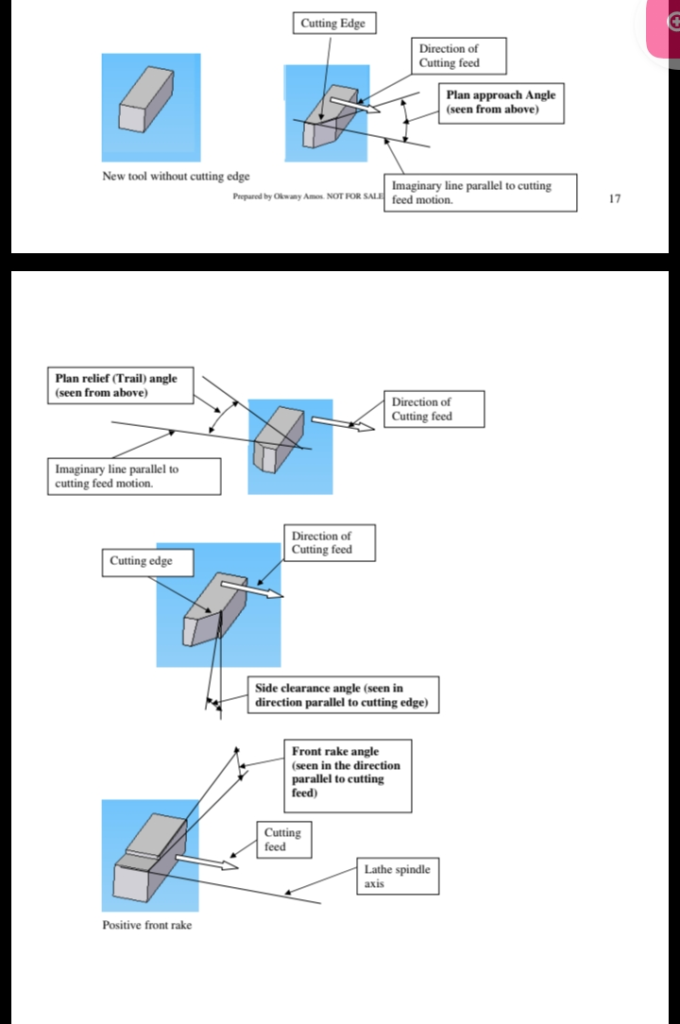
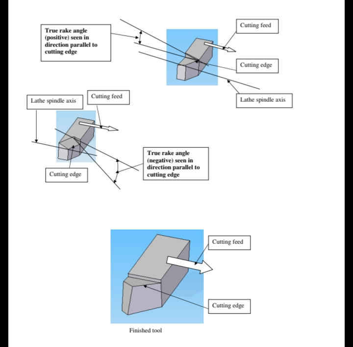
All attempts must be made to understand the position or location of the following angles in relation to the
cutting edge of the tool and some particular motions on the machine. The angles are PLAN APPROACH
angle, PLAN RELIEF (or TRAIL) angle, FRONT CLEARANCE angle, SIDE CLEARANCE angle,
FRONT RAKE, and TRUE RAKE angles. These angles are shone on the turning tool below, but they can
be identified on any other metal cutting tool.